DANIEL LAWSON
Wound VAC
Goal: To build a wound VAC that can achieve -5mmHg for a cost of under $100.
Background
Vacuum Assisted Closure (VAC) is a healing technique that uses a pump to create a pressurized environment around a wound to remove excess exudate and promote healing. A sponge-like material is placed over the womb to which a pressure tube is attached. This process is extremely common post-surgery and dramatically reduces the risk of infection. Modern wound VACs like the ones found in most first-world hospitals start around $500 and feature numerous bells and whistles.

Negative Pressure Therapy

$500 Wound VAC
Like many items in the medical field, the price tag for wound VACs is very high for what it is - just a simple, relatively weak pump. Jonathan Haar, of The Darwin Project, wanted to make a cheap wound VAC to send to his friend Dr. Henry Ndasi's hospital in Cameroon, Africa.
Brainstorm
Since this project was entirely limited by cost, much of the design started with finding cheap parts online and deciding how they can fit together. To keep cost low, we included only the essential components. It was decided that a pressure gauge would be unnecessary so long as the pump was designed so that it could not pull too high pressure. Additionally, we wanted the pump to work with a standard 5V phone charger because most people tend to have those lying around. A 12V version would also be useful for mobile applications in which the user would hook up to a car battery, so we designed for that also.
Component Selection
This is the most up-to-date BOM for the build. The sum of the main components is around $75, leaving an additional $25 per pump for odds and ends like tubing, wires, and sound-suppressive material. We are confident that in the end, each pump will be under our $100 goal.

During VAC, it is common for some fluid and bacteria to get sucked through the hose. To prevent these contaminants from entering the pump, first-world hospitals use one-time-use canisters like the one pictured below. Again, these canisters are over-engineered with many unnecessary features, and the cheapest one we could find was $30. Rather than using expensive canisters, we had the idea to utilize discarded plastic soda bottles instead. Looking on Thingiverse, someone had already made an attachment that matched what we had in mind. However, the previous design allowed for fluid to go directly from inlet to outlet and not get trapped in the bottle, so I altered the design to better fit our needs.

Single-use Canister

Original Cap Design


Updated Cap Design
The change in cap design was in response to feedback from Henry's use of the prototype (seen in video below). A couple of these new caps were printed on Northeastern SLA printers and we are happy with the results.
Schematics
I developed these basic schematics with the component spec. sheets. The thin red and black lines indicate electrical connections while the thicker gray lines are the vacuum tubes. Note that I put together one for 5V to 12V and one for only 12V.

5V Schematic

12V Schematic

Transformer Schematic
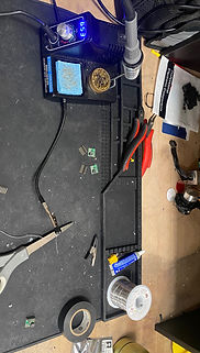
Assembly
Since the transformers came with open pins, I had to solder them to connectors. To connect the wires, I used simple automotive heat and solder connectors. The box was lined with a sound-suppressive foam and the pump was taped down to the foam. Everything fits in the box snugly and is also easily accessible should small repairs be needed.
.png)
.png)
.png)
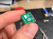
Soldering Tiny Transformers
Electrical Connections
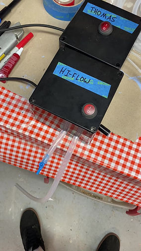
Final Product (For Now)
This video shows the final 2 pumps. The Thomas and Hi-Flow utilize different pumps, so we built a prototype of each to test. The longest tube goes to the bottle cap canister (not shown in the video), and the blue bleed valve is used to control pressure. Lastly, the black short tube on the other side is the exhaust port.

Henry Using Prototype (old cap)
Functioning Prototypes
Next Steps
The new prototypes need to be sent to Henry for testing. We primarily want to test the new cap and the pressure of these new pumps. We are preparing for the next build round of 10 pumps and would like to ship those to an additional 10 doctors that Henry has referred us to located in other parts of Africa. We have begun looking into mass production, primarily of the bottle cap, and found that because of its geometry, it would be cheaper to 3D print than injection mold up to a volume of 500.
The biggest bottleneck in the foreseeable future will be shipping to Africa. As of now, we have not found a viable solution for large volumes. The current shipments of 1-10 pumps are already very expensive and inconsistent.